
I’ve been looking at using an encoder as a front panel control. Encoders are industry standard devices made by ALPS, Panasonic, Bourns and CTS among others. They come with and without a push-button switch and (not-counting the switch) have three terminals, labelled A, B and C.
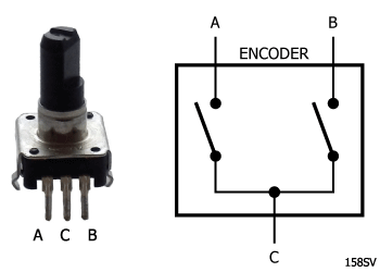
We can connect the C terminal to +Vcc or ground, but the best way to connect is with the C terminal to ground, so that we can use the integral pull-up resistors in the Arduino.

The encoder usually incorporates “detents”. This gives the encoder a fixed number of positions or “clicks” per revolution. For a front panel encoder (as opposed to a shaft encoder, which is used to determine the position of a rotating shaft, such as on a motor), 12 or 24 detents-per-revolution is usual. There will also be a second parameter which relates to the number of pulses-per-detent. Usually, you will want one pulse-per-detent. This means that when you rotate the encoder by one detent, you will get one “set” of quadrature pulses from the encoder.
So what’s all this quadrature nonsense about? Well, as you rotate the encoder, the switches, A and B close and open. In the resting (detent) position, both switches are open, so both the inputs at the Arduino will read high. Between one detent and the next (either direction), both switches will close and open (so at the next detent position, both switches will again be open and both Arduino inputs will again be high). However, the B switch is phase shifted by 90 degrees from the A switch. Since there are four lots of 90 degrees in 360 degrees, the signals are said to be in quadrature.
Here is the “usual” diagram:
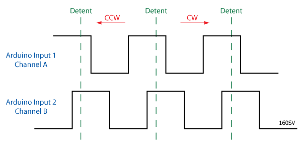
The black lines show what the microcontroller inputs see. When the lines are high, the switches are open and the pull-up resistors are making the inputs high and when the lines are low, the switches are closed, pulling the inputs low.
There are two basic ways of interpreting this diagram. Either way, we start from a detent position.
The first way to read the diagram is to say that each time we transition from one detent to the next, we will get a negative-going pulse on channel A and a negative-going pulse on channel B. If the A pulse starts before the B pulse, the shaft must be turning clockwise. Conversely, if the B pulse starts before the A pulse, the shaft must be turning counter-clockwise.
The second way to read the diagram is to say that at any detent position, channel A is high. When we get a falling edge on channel A, we immediately read the (steady-state) of channel B. If channel B is high, the rotation is clockwise and if channel B is low the rotation is counter-clockwise.
The second method is easier to implement than the first, so that’s the way we’ll go. Here’s another diagram to show this method in more detail:

We start at point x, where the control is at rest in a detent position. The microprocessor waits for A channel A to go low (falling edge). This will happen at y or z. If the control is rotated clockwise, we detect the falling edge at y and read channel B, which is in a steady-state high condition. Conversely, if the control is rotated counter-clockwise, we detect the falling edge at z and read channel B, which this time is in a steady-state low condition. Note that we will not get another falling-edge on the A channel before we reach the next detent position (either direction).
The switches in the encoder are mechanical, we also need to consider bounce. The maximum bounce time for these devices is about 5ms. That’s 10ms of bounce per pulse. There are 100 lots of 10ms in one second. If the encoder has 24 pulses per revolution (say), then at a little over 4 revolutions per second (100/24 = 4.167), the signal would (potentially, worst-case) be all bounce. Fortunately, one revolution per second would be quite fast for a front panel encoder, but let’s assume we’re gunning for two revolutions per second.
At 24 pulses per revolution, 2 revolutions per second is 48 pulses per second. So the pulse width is ~20ms. In our software, we wait for a falling edge on channel A, then read channel B. Channel B is read in the middle of a steady state which is ~10ms wide, so we should be past any bounce on channel B. Therefore, as long as we don’t try and read channel A more often than once every 5ms, we don’t need to de-bounce either of the channels.
Nonetheless, it is a good idea to de-bounce anyway, so here’s a little test circuit and some Arduino code.
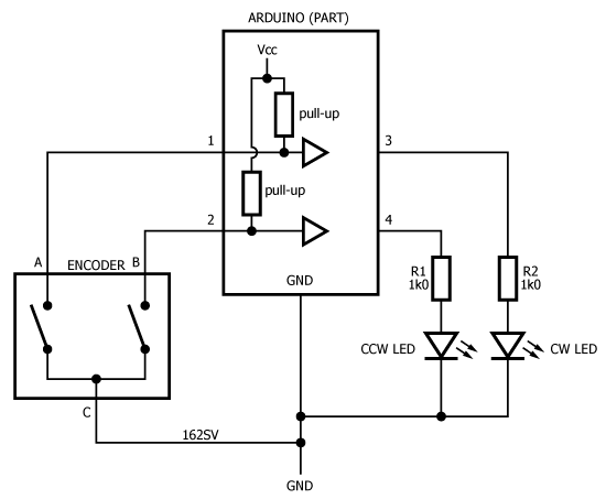
The idea is we detect a rotation and flash the corresponding LED. If we turn the encoder slowly, we will see each pulse individually. As we get faster, the pulses tend to blend into one.
#include <Bounce.h>

#define channelApin 1
#define channelBpin 2
#define cwLEDpin 3
#define ccwLEDpin 4

//
//setup switch debounce
//
Bounce channelA = Bounce (channelApin,5);//5ms bounce time
Bounce channelB = Bounce (channelBpin,5);

//
//setup
//
void setup() {
  //initialise pins
  pinMode(cwLEDpin, OUTPUT);
  pinMode(ccwLEDpin, OUTPUT);
  pinMode(channelApin, INPUT);
  pinMode(channelBpin, INPUT);

  //write pin defaults
  digitalWrite(channelApin, HIGH); //pullup
  digitalWrite(channelBpin, HIGH); //pullup
  digitalWrite(cwLEDpin, LOW); //off
  digitalWrite(ccwLEDpin, LOW); //off

  //clear bounce buffers
  channelA.update();
  channelB.update();
}

//
//main
//
void loop(){
  channelA.update();
  channelB.update();
  if (channelA.fallingEdge()==true){
    if (channelB.read()==true) digitalWrite(cwLEDpin,HIGH);
    else digitalWrite(ccwLEDpin,HIGH);
    delay(10);
    digitalWrite(cwLEDpin,LOW);
    digitalWrite(ccwLEDpin,LOW);
  }
}
It’s worth noting that this code doesn’t work perfectly at high speed; if you really give the control knob a good fast spin clockwise (say), a few counterclockwise pulses will be registered. But that’s OK. If you want fine control it works perfectly and if you only get 99 clockwise pules for 100 detents when you go fast, it’s hardly a problem. On the plus side, the code is really easy to implement. ![]()