
In my introduction to theatrical lighting systems I considered the many and varied lighting installations you might find in a performance venue and talked about independent power control which we will discuss further here.
In days gone by, practically all of the performance luminaires in a theatrical installation would use filament lamps and be suitable for dimming with a hard-fired dimmer. DMX would only be used to connect the lighting desk (or board or console) in the lighting booth to the dimmer racks backstage.
Nowadays, hard-dimmable lanterns are a declining proportion of the luminaires and devices deployed in a theatrical installation. Many modern devices require full mains power and direct low-voltage control.
It is possible to power up modern devices from the lighting desk but there is a risk associated with inadvertently dimming a device which only accepts full power or accidentally powering down a luminaire with a discharge lamp (which then takes a few minutes before the lamp will re-strike).
Consequently, we need other ways of remote-controlling stage outlets and there are a number of ways we can do so:
- Plug the device into a permanent live outlet and don’t turn it off.
- Plug the device into a permanent live outlet and physically walk up to the device to switch it on/off for every performance.
- Switch the outlet from the dimmer room.
- Switch a group of outlets using a large load-switch in the dimmer room.
- Remotely switch a group of outlets using a contactor or motorised-MCCB in the dimmer room (controlled locally or from the lighting booth).
- Install an independent contactor rack alongside the dimmer rack (controlled locally or from the lighting booth).
The one thing you should not do is use MCBs in the distribution board to turn circuits on or off – they are not designed to regularly switch circuits on-load and you don’t want them to fail when you need them to prevent a fire.
Option 1 may well not be acceptable for several reasons, including: a desire to extend the life of the device by not having it powered-up unnecessarily, safety, fire prevention, and the cost of wasted energy.
Option 2 may well be inconvenient, time consuming, prone to error and unnecessarily hazard-prone.
Options 3 and 4 are better than Options 1 and 2 but do not have a facility for remote control or remote monitoring.
Options 5 and 6 offer the best flexibility at the highest cost.
Remote control potentially has the following benefits:
- The dimmer room can remain locked during normal theatre activities
- Circuit status can be remotely monitored
- Circuits can be individually or collectively remotely switched
- Automatic emergency shut-down can be integrated into the fire-alarm/evacuation system
- Manual emergency shut-down points can be deployed at strategic locations (e.g. adjacent to the Stage Manager’s console).
Main Electrical Supply
Here is a diagram of how the main electrical installation might be deployed:

The above illustration shows a sub-main delivering power to the dimmer room. The sub-main feeds an MCCB distribution board (via an isolating switch) which distributes the sub-main into several sub-sub-mains. For this article, we are interested in the sub-sub-main titled “stage power outlets” which will supply outlets on, above and in-front-of the stage for theatrical performance equipment (lighting, sound, practical props and special effects).
 Fuses Protect Cables
The Wiring Regulations and other national electrical codes were developed at the end of the nineteenth century to ensure that electrical installations were designed and deployed in such a way so as to minimise the likelihood of fire. Over the years, the regulations have increased in scope to improve protection against the effects of electric shock, but it cannot be stressed too highly that the main purpose of fuses and other over-current protective devices is to prevent smoke and fire.
As such, within the fixed electrical installation, fuses (and MCBs, MCCBs) are deployed so as to protect the downstream cable. Fusing within the fixed installation is not fundamentally there to protect appliances, nor is it there to protect against electric shocks or even the upstream cable. This is a mantra to remember.
Fuses, MCBs, MCCBs, Switches, Disconnectors, Relays and Contactors
Fuses – are designed to be the weakest point in an electrical circuit and hopefully will disconnect the supply safely in the event of a fault. Fuses have a nominal current-carrying rating and a breaking capacity. The current carrying rating is that current which the fuse will allow to pass indefinitely (under specified temperature conditions). The breaking capacity is the maximum current the fuse can safely interrupt in the event of a fault (short circuit). Glass fuses have low breaking capacity and should only be used inside appliances. Fuses in the installation (including dimmer output fuses) should be ceramic HRC (high-rupture-capacity) types.
MCB – stands for Miniature Circuit Breaker. There are different types of MCB, but in this context, MCBs are thermal-magnetic. You can also find (in other circumstances) thermal-only and magnetic-only circuit breakers.
The “thermal” part is a resistance wire deployed adjacent to a bi-metallic strip. This mechanism trips the circuit if the long term load-current rises above the nominal rating of the MCB. So, if you connect a 33A load to a 32A MCB, you can expect the MCB to trip in about an hour. If you connect a 40A load to a 32A circuit breaker, you can expect the MCB to trip within a few minutes.
The “magnetic” part is a solenoid. This mechanism trips the circuit very fast if there is a very high current or short circuit. The thermal part would also trip under such conditions but is too slow for safety.
MCBs are typically rated for holding currents between 1Amp and 63Amps. MCBs are ‘miniature’ because they are a small version of an MCCB.
MCCB – stands for Moulded Case Circuit Breaker. An MCCB is similar to an MCB, but is physically larger, can safely break a much larger fault current and often has options for auxiliary contacts and remote-control.
MCCBs are typically rated for holding currents between 16Amps and 1000Amps.
Switches and Disconnectors notionally do the same thing, i.e. disconnect the circuit from the supply and thereby switch the circuit off – but switching and disconnection are not technically the same thing.
Disconnection – means disconnecting (i.e. isolating) the supply in a way which is deemed safe for a technician to perform maintenance work on the downstream installation or connected appliance. Disconnectors have a mechanical action that holds the contacts open with strong spring-pressure (so it is difficult to accidentally switch the circuit on) and they switch all of the circuit conductors i.e. live (hot) and neutral (cold), including all phases in a multi-phase system. Disconnectors also maintain a minimum contact-separation gap in the isolated position. Disconnectors have a nominal carrying-current, but often have a zero amps switching-current rating. That is to say disconnectors should only be operated when there is little or no current flowing through them.
Switching – means switching a circuit under full, partial or no load – or even overload. Switches may or may not be isolating. Switching-current rating will vary according to the type of load (resistive, inductive, etc) and duty-category (how often the switch is expected to switch full load).
Switch Disconnector – a device which provides both a load-switching and disconnecting (isolating) function.
Relay – an electromagnetic switch. A relay comprises a solenoid (called the coil) which operates electrical contacts when energised. The coil circuit is electrically isolated from the switching contacts. Relays may be used so that a low-voltage low-power control signal may switch a mains-voltage high-power signal (which is useful in itself) and have the advantage that the switching action may be performed remotely – you only have to deploy a low-voltage low-power control line to the remote location instead of routing a large power cable.
Contactor – a relay on steroids. Similar in concept to MCCB vs MCB – a contactor generally has a higher current switching capacity than a relay; it also has a better duty category and you can fit accessories and auxiliary contacts to a contactor.
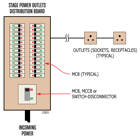
Local Switching
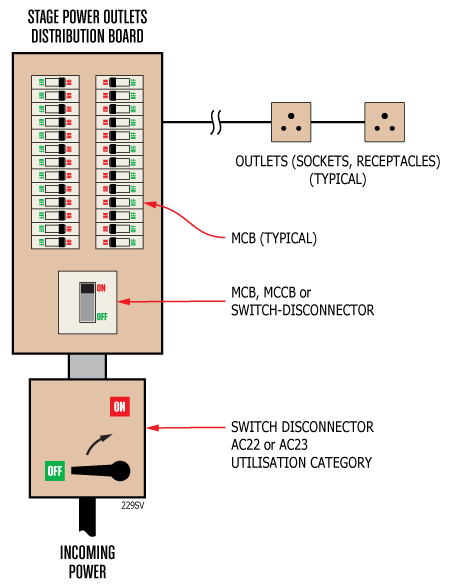
In the illustration above, the stage power outlet distribution board may incorporate a switch-disconnector, MCB or MCCB on the input. None of these devices are suitable for regular (daily) load switching. It is a common misconception that any switch or circuit breaker is suitable for use as an on-load switch but this is not the case. Switches designed for regular on-load use are considerably heavier-duty than protection/isolating devices designed for occasional maintenance or emergency switching. Therefore a specific load-breaking switch (rated AC22 or AC23 utilization category) should be added if it is intended to switch all the stage power outlets together before and after a performance:
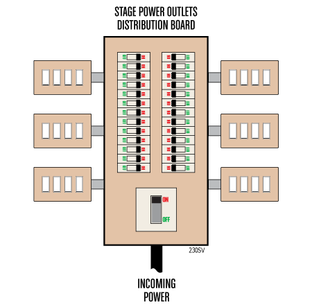
The obvious alternative to the above all-or-nothing solution is to switch each individual circuit separately. Again it should be emphasised that individual MCBs on the distribution board should not be used for regular load switching. Instead, downstream switches should be deployed. One solution is to deploy 16A single-phase circuits each protected by a 10A or 16A MCB and switched with a 20AX switch. The X-suffix indicates that the switch is suitable for inductive loads. Such switches are available in a grid-switch form-factor so banks of such switches may be made up:
Remote Switching
As with local switching you can either switch the input side of a distribution board and have an all-or-nothing control or you can individually switch each circuit or group of circuits.
To switch on the input side you have two options: either a motorised MCCB or a contactor.
Despite my grave warnings about using protective devices to regularly switch on-load, there are available MCCBs with an AC23 utilisation category which are suitable for connecting and disconnecting under load. Such MCCBs may also have an auxiliary module with a solenoid trip and a motorised closer. Thus they may be remotely controlled using a low-power control circuit.
An alternative is to use a contactor to connect and disconnect the incoming power to the distribution board. In this case it will be necessary to employ a contactor with an AC3 current rating equal to or in excess of the distribution board current rating.
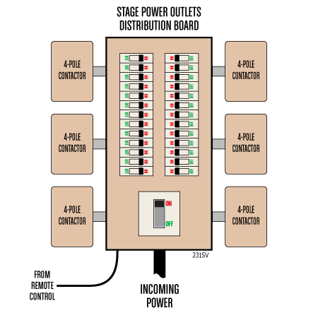
To switch on the output side, you either employ an individual contactor for each final circuit or use multi-pole contactors to switch final circuits in groups of three or four (as contactors generally are available in 3-pole or 4-pole versions and you only need to switch the live of a single-phase circuit).
You could deploy contactors on-the-wall in place of the switches in the illustration above:
Alternatively, you could have a separate independent contactor rack. An independent contactor rack usually does the job of the distribution board as well: In the next part we will look at design architectures and schematics for independent contactor racks.
 ![]()