
In the first part of this series, we introduced the idea of power control separate from the dimmer system and gave an overview of different ways we can manage switching of power to installed appliances. In this second part, we will look at remote-control schemas for independent contactors.
One Big Relay
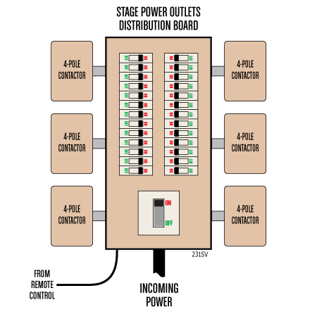
So, the first option is to switch the incoming supply to the stage-power distribution board:

As previously noted, the contactor will need an AC3 rating. If an MCCB is employed, it will need an AC23 rating. In either case, the rating must be equal to or higher than the maximum nominal incoming current.
Conventional control circuitry
Here is the schematic for a conventional no-volt-release control circuit: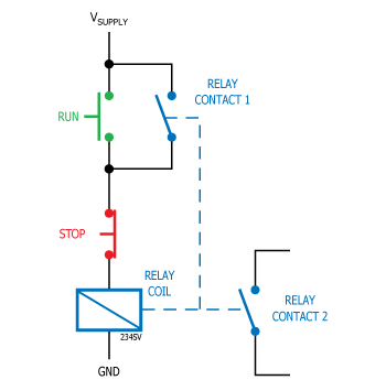 The idea is that the RUN and STOP switches have momentary action (so they return to the positions shown on the above schematic when released). When you press the RUN switch, the circuit to the relay coil is completed and the relay is energised. Relay Contact 1 then latches the action of the RUN switch so that when you release the RUN switch the relay stays on. If, however, you lose power (Vsupply is switched off) or you press the STOP switch, the relay de-energises and Relay Contact 1 opens. If Vsupply fails then the circuit will not re-start when Vsupply is restored – the RUN switch must be pressed again to re-energise the circuit. Meanwhile Relay Contact 2 is doing something useful.
The big advantage for this type of circuit is that we can add multiple ‘run’ and ‘stop’ switches and they all work independently:
As you can see, if we press either of the ‘RUN’ switches then the circuit will be energised and if we press either of the ‘STOP’ switches, the circuit will be de-energised. Thus, using just three wires, we can locate RUN1 and STOP1 at a remote location (say in the lighting booth) from RUN2 and STOP2:

However, we need an indication of whether the circuit is on of off, so we have added indicators to show the status of the control cicruit.
Doubling up
If we had more than one large contactor in the dimmer room, we could duplicate the above scheme for each contactor. At the remote end, Vsupply and ground are common to all circuits. So a full schematic for two contactors might look like this: We could probably expand this to four or six contactors and implement grouped contactor control like this:
 However, six contactors would require a 20-way control cable which is starting to get unwieldy. As the number of contactors increases we need to consider multiplexed controls.
DMX to the rescue?
It is tempting to control independent contactors using DMX but if we do, we are getting dangerously close to the reasons why we took these power controls off the lighting desk in the first place.
As previously noted, we want to control the power to lighting and sound appliances which must not be hard-dimmed and must not be accidentally switched off during a performance. Consequently, we don’t want them controlled from the lighting console as there is a danger that a programming error or system crash will cause one or both of the above eventualities. Using DMX to control the independent contactors – even if we use a separate control surface from the main lighting console – is still potentially fraught with danger because the DMX deployment within a venue is dynamic – different show-lighting schemes may require different DMX topologies. So if we do use DMX, it should be an entirely separate universe to the main DMX system and it must be directly wired between the remote control station and the independent contactor rack. However, the main problem with DMX is that it is a one way protocol with no error or sanity checking and for that reason DMX is not ideal.
A similar argument applies to Ethernet control in the sense that Ethernet could be accidentally un-patched.
Serial Protocols
If not DMX then what? Well, if you are planning a single end-to-end link between the lighting booth and the dimmer room, you could implement a simple bespoke protocol over RS422 on shielded twisted-pair cable such as Belden 9842. RS422 over two twisted pairs allows for a transmit pair and a receive pair. Bus speed would be very slow (even as low as 9600 baud) for good reliability and transmission distance. The protocol could be ASCII so you could read and emulate it using a terminal on a laptop (with a suitable USB-RS422 adapter, natch).
For a system with multiple remote stations, you could implement an RS485 multi-drop network or even adopt a protocol such as CAN-BUS (specifically low-speed high-integrity mode).
As CAN-bus only requires a single twisted pair, you could run it over your Cat5e infrastructure cabling if you have a small venue. However, over longer distances the resistance of the puny wires in Cat5e becomes significant and will affect the necessary termination resistance. Also, some companies recommend that you use a shielded cable for CAN-bus so DMX installation cable (not flexible cord) is a good starting point.
RS485
With a multi-drop network you can have about 64 or so nodes depending on your physical network design and termination. Your independent contactor rack(s) in the dimmer room will be one end of the network daisy chain and the remote panel in the lighting booth will be the other end of the daisy chain. In between, you could have a local control panels on catwalks over the auditorium; a status/control panel adjacent to the stage manager’s desk; local control panels on the fly rail, etc. You could also deploy an interface to the fire alarm system and/or voice evacuation system to switch off certain circuits in the event of an alarm condition.
The software should allow for individual circuit control or grouping and should also allow for sequenced-switching (both on and off) to reduce the negative effects of step load-changes on the mains infrastructure.
In the next article, we will consider a standard protocol for independent contactor rack control. ![]()