
Phantom Piezo Preamp Modules are available from the shop here.
Sometimes, back-of-the-envelope calculations do not tell the whole story (and neither do simulations). This article is a follow-up to the original article Phantom Piezo Preamp and addresses some errors and misconceptions that have arisen.
The Phantom piezo preamp module (available in the shop here) has been very popular and has sold well. Occasionally though, we have had questions – both in the comments and privately – which I have addressed as best I can. However, confidence in my answers has not been as high as it should be, so I invested in a Focusrite Scarlett 2i2 and downloaded ARTA audio measurement and analysis software and set to work taking a new look at the performance of the Phantom Piezo Preamp.
Low frequency response and input impedance
Here’s a reminder of the original design schematic:

In the original article, we suggested that the 220pF coupling capacitors (C2 and C3) were too low in value to give good low-frequency coupling; we suggested an increase to 22nF along with an increase in value of R1, R2, R5 and R6 to 3M3 (along with some other changes – see the final schematic below). We suggested that the -3dB lower corner frequency improves to 22Hz with these values. Our back-of-an-envelope calculations suggested that the effective input impedance is 3M3 and the lower -3dB corner frequency should therefore be 1/(2*Pi*R*C) where R equals 3M3 and C equals 11nF (two 22nF in series) which equates to 4.4Hz. However, we cite a -3dB corner frequency of 22Hz – which we understood from the LTspice simulation. I did not originally do the calculation which gives 4.4Hz, so I didn’t notice the discrepancy.
Here’s a reminder of the final schematic: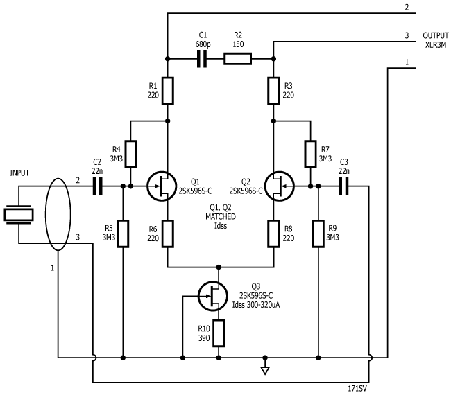
If we plot the actual frequency response of the above design using ARTA, we get this (click for a larger image):
 As you can see, the lower -3dB point is at about 8.5Hz. This suggests that neither our back-of-an-envelope assessment nor the simulation is correct. Assuming the input capacitance is 11nF, we can calculate (from the 1/(2*Pi*R*C) formula) the input resistance as 1.7 M Ohms. This suggests that we should not have included the values of R4 and R7 in our initial assessment and the input resistance is set by R5 || R9.
Note that the actual system low-frequency response you will see is a function of the coupling between the Phantom Preamp and the characteristics of the input stage of the following microphone preamp.
High frequency response
The high frequency response is moderated by the Zobel network formed by C1 and R2 in the above schematic. To increase the high frequency response we would need to lower the value of C1 as follows:

Changing the input impedance
There has been some interest in increasing the input impedance of the design and – based on the original article – there is a natural tendency to increase the values of R4, R5, R7 and R9 to a higher value. However, we note above that the input impedance is set by R5 || R9 only. If we replace R5 and R9 with 10M Ohm, the input impedance will increase to 5M Ohm. An alternative solution would be to connect the piezo transducer with series resistors. You could just use one resistor, but two equal value resistors, one each connected at pins 2 and 3 on the input would be more balanced. So, if you wanted to increase the input resistance to about 10M Ohm, (say) you would add a 3.9M Ohm resistor in series with each of the piezo-transducer connections to give an input impedance of 3.9 + 3.9 + 1.7 = 9.5 M Ohm. Note that this would reduce the input sensitivity by 15dB as the added series resistors would make a potential divider with R5 and R9. Also, note that very high resistance values may exhibit significant self-noise (Johnson noise), so there is a trade-off between input impedance and noise.
Finally, be aware that if you change the value of R5/R9 (without changing R4/R7) you will change the bias point of Q1 and Q2. This will affect input headroom. E.g. if you increase R5/R9 to 10MOhm, the d.c. operating point at the gate of Q1/Q2 will increase from ~22V to ~33V.
I hope this clarifies the situation further and welcome any comments either below or by email. ![]()
I would like to enclose the preamp in a small case.
Any tips or concerns to avoid RF issues?
Thank you!
Best wishes
Not really, just put it in a metal enclosure and keep it as close to the piezo transducer as possible. If you can’t have a short wire to the piezo transducer then you should connect the piezo with shielded balanced cable and fit a suitable input connector to your enclosure.
THANK YOU!
Hi. I would like to know the details of capacitors.
Is it film capacitor or any other type..?
Thanks
Yes, film capacitors – polyester (PET, Mylar) or polypropylene.
Hi.I’d like to decrease the input impedance from the piezo which I only use 1 and still distorting on the way in.
Is there any way to keep the frequency response and only decrease the input impedance. If there is any trade off to losing low frequency, I’m ok to lose up until 100-160hz.
Also, Can you advice me on Q3 substitution that has similar specs.
Thanks.
Input impedance is set by R5 and R9. R5 and R9 should be the same value and the input impedance is half of this value. So if you wanted an input impedance of (say) 500k, the value of R5 and R9 should be 1MOhm. If you drop the values of R5 and R9 to 470k, the lower -3db point rises to about 30Hz.
You can use a wide range of JFETs for this design (e.g. 2N5457/8/9 2N5485/6/7, PF5102/3, BF256B). The main criteria are that Q1, Q2 are very closely matched and that you set the value of R10 to suit the current you want to flow in Q3 which should be in the range 0.1-0.5mA.
Hi. Thanks for the quick response.
I have another question for you that I messed up my circuit while I trying to change the resistor. Now its only making hissing noise and no input signal detected. I was trying to desolder R5,R9 and one of them took sometime, I might have fried some component.
How can I troubleshoot and where to start..? What is most likely the culprit..?
Thanks
I expect you have damaged one or both of the JFETs. None of the other components are likely to have suffered overmuch from getting too hot.
I’d built a circuit based on the original design before finding your version. I’ve made a new version based on the diagrams here but running into problems with the gain. I’m using 2n3819 FETs with a 1k for r10 and 10M for R5 and R9.
When attached to my mixing desk the signal is so strong I have to have the pre-amp very low or the signal clips. I’v tried increasing R10 to 5.6k (in steps) and that didn’t help. I’ve also inceased R6 and R8 up to 1k (again in steps) which also didn’t help.
What am I doing wrong ? Any help gratefully received.
Firstly, I reccommend you set R10 so that the current in Q3 is 200-500uA and adjust the gain in other ways.
Don’t forget that R4/R5 form a potential divider to bias the FET and by increasing R5 to 10 MOhm, you have changed the bias point significantly. I recommend you reduce R5/R9 back to 3.3Meg and try adding series resistors to the input as per the final paragraph above.
Thanks for the reply, sorry for stupid questions but I know just about enough to follow a circuit diagram 😉 how do I calculate R10? in the other blog post on this desugn you say “Put a resistor in (say 2k2) and measure the voltage drop. Use Ohm’s law to get the current. Change R10 as appropriate” where am I measuring the voltage, across R10 ? If that’s the case I’m confused coz with R10 @ 2k the voltage is 3.7v meaning I=1.85mA which is abiut 4x too high yet the docs on the original Alex rice version say to use 1k to 2k for R10 with 2n3819’s
The bias current is not too important. The reason I suggest 0.2~0.5 mA is because the higher the bias current, the more the supply voltage is pulled down. 1.85mA is certainly not too high to cause a significant problem. In your case I would increase R10 to (say) 4.7k and get the bias current below 1mA.
Hello!
Will you update the schematics and instructions to correspond to the new (V2) phantom powered piezo preamp?
Thanks
You can download the instructions from the shop. The schematic is practically identical apart from the addition of two 4.7V Zener diodes across the input. I will update when I get a moment.
Regards.