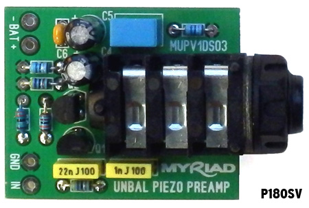
Update: Modules are available in the shop here now.
I finally decided to retire the Altoids Piezo Preamp Kit and Altoids Piezo DI kit projects from the shop; I received good feedback from customers – but not enough people bought them. Fully built and tested Altoids Piezo Preamps are available from the shop here.
The Phantom Piezo Preamp Module has been a great success and has sold very well. However, we have been getting a significant number of enquiries about deploying the Phantom Piezo Preamp without the Phantom power so I decided to adapt the Altoids Piezo Preamp design to make a complimentary module to the Phantom Piezo Preamp. In the absence of a better idea, I am calling it the Unbalanced Piezo Preamp. Here is the schematic:
This is a slightly cut-down version of the Altoids Piezo Preamp design. It is worth noting that this is an impedance buffer rather than a preamp as it has no voltage gain (in fact the voltage gain is slightly less than unity). Battery life is a few hundred hours and the design will work down to about 4V. If you want to connect a quantity of these up to a power supply (which must be smoothed and regulated), the maximum supply voltage is 24V (but there is little mileage in going above 15-18V). If you do connect several preamps to a power supply then you should create a star grounding point adjacent to the power supply output and take the negative battery wires separately from each channel to the power supply -ve.
The PCB is 38mm x 31mm (approx 1.5″ x 1.25″). Input and battery connections are via solder pads. However, space has been allowed to fit terminal blocks with 3.81mm (0.15″) spacing. Terminals will be available in the shop as an optional extra. Output connection is a stereo jack socket which takes a mono jack plug. The output is wired so the battery negative is disconnected when there is no plug inserted in the output jack. If you don’t want this functionality, you need to solder a link between the ring and shield connections for the output jack. Do not be confused by the stereo jack on the output – both the input and output of this design are wired unbalanced.

If you want to experiment with this design, here’s the low down:
- R1 and C1 form a low-pass filter to keep RF interference out of the system.
- C2 sets the low-frequency response at the input.
- R2 sets the input impedance. You can increase this up to about 10M Ohms.
- R3 sets the bias current in Q1.
- C3 sets the low-frequency response at the output.
- R4 applies a nominal load to the output to discharge C3 and avoid thumps.
- R5, R6 set the d.c. operating point at the source of Q1 (which should be about 1/2 Vcc).
Note that the system low-frequency response depends on the coupling capacitance and input impedance of the following stage. This circuit will drive into an input as low as 10k input impedance before the low-frequency -3dB point rises above 20Hz. If you want better low-frequency response into a low impedance input then you will need to increase the value of C3 (up to 47uF 16V +ve towards JFET’s). What can I use it for?
You can use it to buffer a piezo transducer or pickup in a cigar box guitar (or any other stringed instrument), a cajon or a stomp board/block. You can use it in an art-installation to percussively create sound effects. You can use it as a buffer fro a passive piezo hydrophone transducer. You can use it as an electric guitar buffer to protect against long-guitar-lead and/or effects-pedal tone-suckage. If you want to build a buffer pedal, you should consider the JFET guitar buffer project.
Unbalanced Piezo Preamp Modules are available to buy in the shop here. ![]()


Inspired by the following articles:
http://www.jimdunlop.com/blog/what-you-need-to-know-about-true-bypassing/
http://www.petecornish.co.uk/case_against_true_bypass.html
Could this described circuit be attached to the ‘bypass’ pins of RL1 on your “ATRelay with mute”,
(http://stompville.co.uk/?p=423 ) to function as a unit gain/buffer, when in true bypass mode ?
The Jim Dunlop article is OK regarding different types of bypass, but the bit about buffers is not OK.
When he talks about degradation, he’s talking about loss of high-frequency components in your signal. He’s suggesting that a buffer can automagically detect the amount of loss and automatically compensate. This is not true.
Pete Cornish is not making a case against true bypass, he’s making a case in favour of buffering – which is good – but then goes on to suggest that only his special-sauce super-complicated preamp circuitry will do. This is elitist nonsense.
There is a case for true-bypass and there is a case for buffering. The above design is ideal to buffer your guitar signal (or have a look at the JFET Guitar buffer version of this product here). If you use a longish guitar lead, you will notice a huge difference in your tone – your guitar will sound super bright. However, you only need to buffer once – directly before your effects chain – unless you have some particularly poorly designed effect which has major tone suckage.
But to answer your question, yes absolutely this could be used as a buffer in true-bypass mode.