Updated – see below for information on improving the design to lower the output impedance.
We have had enquiries about adding volume and tone controls to the Unbalanced Piezo Preamp (available in the shop here). The PCB was not designed for the addition of these controls, so this article represents something of a hack.
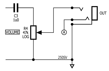
Here’s the schematic for the design as it stands:

The purpose of R4 in the design is to discharge C3 when the output is disconnected. The value of R4 is not too important although we generally make it high because it forms a high-pass filter with C3.
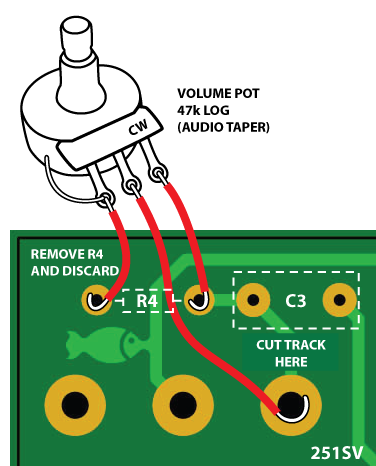
The best way to add a volume control is to remove R4 and replace it with a potentiometer:

We are going to put a potentiometer with lower resistance than the value of R4. This is because the potentiometer affects the output impedance of the circuit (which we want to keep low). The pot value should be 47k (or 50k depending on manufacturer).
To add a potentiometer, we need to remove R4 and cut the PCB track between the C3/R4 junction and the output jack. Then we need to wire the potentiometer in place of R4 and connect the wiper to the output jack:

If you have not cut a PCB track before, the best way is to get a sharp knife (such as a small craft knife, Exacto or scalpel) and make two cuts perpendicular to the alignment of the track. Then take your soldering iron and use it as a chisel to remove the cut section. The track between the cut lines should come off cleanly in one piece.
Adding a tone control
We can add a tone control as well as volume. The tone control is similar to that on an electric guitar – i.e. the effect of the control is going to be treble-cut only.
You can visit any of many websites and get different ideas for wiring volume and tone controls and this is just one idea you could try.
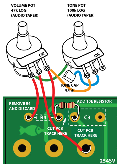
To add volume and tone controls, we need to cut PCB tracks in two places and install a 10k resistor. Then wire up as per the sketch below.


The wiring scheme above shows the conventional method of grounding the potentiometer bodies. You may not need to do this but you probably should.
Lowering the output impedance of the preamp.
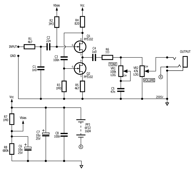
I have been given a heads-up about a circuit topology called the Borbely Follower which aims to significantly decrease the output impedance of the preamp and thus improve the performance of tacked-on passive tone controls. Regrettably, I have not had time to experiment with this arrangement so I can only offer the following as something you can play with if you’re interested. The topology adds two resistors and capacitor to the original design, which now looks like this:

You may need to adjust the value of R4 and you will need to find a value for R6 which is less than 10k and greater than zero – the lower the better. If you get good luck with this design, please do leave comments below. ![]()
