
We have had a few enquiries about using the true bypass relay board with the control switch remote from the board itself (original article here) (kits available in the shop here). We should emphasise that as it stands, the true bypass board is designed for the ‘Stomp Here’ switch to be mounted in the same box and very close to the board. Here’s the original schematic:
In order to remote the ‘Stomp Here’ switch we need to consider switch debouncing, noise immunity and microcontroller input protection.
Atmel Digital Input
The microcontroller input can be modeled like this:

The external signal connects to PB1. Diodes D1 and D2 provide ESD protection to the input. Cin represents parasitic input capacitance and is very low (<10pF). Rpu is the pull-up resistor with a value between 20k and 50k. Q1 connects Rpu to Vcc and is controlled by the pull-up disable (PUD) signal. The input signal passes through a Schmitt trigger to square-it-up and then (via the synchroniser) becomes a logic bit in the PINB register.
As it stands, we rely on the pull-up resistor Rpu to hold the input (PB1) at 5V unless we ground the input using the ‘Stomp Here’ switch. We rely on the Schmitt trigger to create a nice (square, fast) edge to our logic signal and we use a software debouncing algorithm to ensure that one press of the switch gives one signal to the switching part of the software.
Design Limitations
Limitations of simply connecting a switch to ground include the notion that D1 and D2 are not particularly robust, Rpu is considered a “weak” pull-up and Cin has a very low value.
Option 1 – Beefing-up the Input circuitry
We will offer two ways to make the microcontroller input more robust. Firstly, we can add some extra components adjacent to the microcontroller input: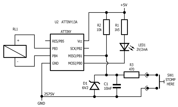
Here R2 strengthens the pull-up. Zener diode D1 prevents the input going higher than nominal 6.2V. R3 forms a low-pass filter with C1 which filters out RF interference. If you’re feeling confident, you can omit D1. D1 could also be 5V6 (or even 5v1 at a pinch).
Option 2 – adding a photocoupler
Another option is to isolate the microcontroller input using a photocoupler. Many jelly-bean parts will do, but if you’re buying a new one, buy something with 817 in the part number, e.g. Sharp PC817, Kingbright KB817, Fairchild FOD817, Vishay K817, Avago HCPL-817, etc.

The advantage here is that we only need to add two components instead of four – but the photocoupler is slightly more painful to implement without a PCB or stripboard. Because there is no signal into the microcontroller unless the LED is on, the system is largely immune to EMC issues when the switch is not pressed. When the switch is pressed, the circuit is fairly low impedance (about 2.5mA through the photocoupler LED) so again, EMC should not be a problem.
Debouncing
Note that the software debounce is only good for about 64ms of debounce time, so you do need to implement a proper switch. Some customers have complained that the relay switches erratically – however, on investigation, in every case, the problem has occurred in a prototype scenario where a proper stomp switch was not implemented.
If you choose to mock something up on your workbench, you may notice that the software debounce will not cope with you switching by touching a piece of grounded jumper wire to the microcontroller input.
Unexpected switching behavior
If you’re using the kit (available from the shop here) and you are getting odd switching behavior, this may be because you don’t have an LED fitted. Please see the latest version of the User Guide here under the download tab. ![]()