
Update – extra schematics and timing diagrams added (see below). Also TLP222G photo mosfets are available in the shop here.
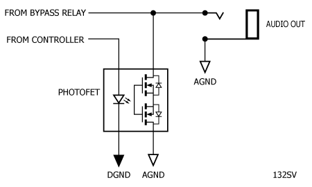
There has been discussion on Stompville here (in the comment section) and on diystompboxes.com about problems with audio clicks when using a relay for true bypass. The consensus seems to be that the answer is to use a photofet opto-isolator to mute the audio output while the relay is switching. Two components in particular have been discussed, the Toshiba TLP222G and the Fairchild H11F1M.
These devices are called photofet isolators and comprise an LED (the input or control side) optically isolated from a push-pull MOSFET (the output or detector side). There is no external gate connection to the detector and the output stage is switched on by the light coming from the LED. Our intention is to use the MOSFET to short the audio signal to ground (i.e. mute the signal), then switch the relay, then release the mute. The opto isolator function allows us to separate the control signal (from our micro-controller) and the audio signal (from our bypass relay) and in particular have separate (or managed) analogue and digital grounds.
Now, we could just switch the LED on when we want to mute and this will probably work adequately in most cases. However, it would be more elegant if we could have a soft mute so the sound would fade out over a period of time (say 20 ms) then we switch the relay, then un-mute over a further 20ms, giving a total switching time of 50 ms (allowing 10 ms for the relay to change-over).
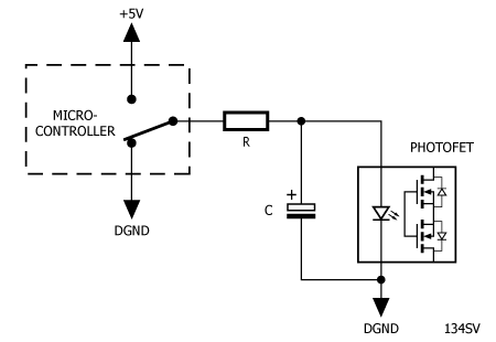
To cut a long story short, the TLP222G is a better option all round than the H11F1M (more on this later), so I have been experimenting with the ‘222. The following circuit has been suggested as a way of providing soft mute:
Unfortunately, the switching characteristic of the ‘222 is such that the above circuit simply delays switching of the output stage and does not provide a soft muting function.
Another possible option would be to use PWM control of the LED current:

Unfortunately, the switching characteristic of the ‘222 does not lend itself to this solution because the maximum useable PWM frequency for the ‘222 is less than 5kHz (which is, of course, audible). We would need a PWM frequency of 40kHz or higher to make this circuit useable.
However, if we hard-switch the LED (i.e. don’t use PWM), but make the resistor R fairly large, we can at least ramp the audio down:
Here’s a timing diagram for the above with an LED current (set by R) of about 2mA:

However, there is a caveat here as well. I bought a batch of 25 TLP222G’s and after trying only about half a dozen of them it became clear that the resistor required to give the 20 ms mute period is a moveable feast and would need to be selected for the individual sample of TLP222G you have – which is OK if you have an oscilloscope handy.
So it seems the way forward is to forget trying to force a soft mute of the photofet for the time being – I will continue to tinker with any ideas which come to mind. We should set the value of R low enough to make sure that any sample of the TLP222G will fire reliably. That value would coincide with a If of 3mA and the resistance would be (5V – 1.15V)/3mA = 1.28k so 1.5k would be adequate. This gives us our timings as follows:


Note that if you want to muck about with the soft mute, I have left a 20 ms delay before operating the relay. R2 will need to be in the region of 3.6k – 5.6k. You might consider a 1.5k resistor with a 5k preset in series.
As previously noted, U1 could be LP2950-5V to save battery life; U2 could be ATtiny13 in lieu of ATtiny13A; and finally, U3 could be TLP222A. R1 may need to be reduced if your LED is too dim.
Here’s a link to firmware hex file with timings as per figure 142SV above. No fuse changes required.
TLP222G’s are available for sale in the Stompville Shop.
Update – Where should the Capacitor go?
I’ve received a few comments suggesting that the electrolytic capacitor should go before the resistor and this will make all the difference. In fact it makes no difference. We can’t escape from two facts we have discovered:
- The photofet has sharp turn-on and turn-off characteristics
- The actual characteristics vary significantly from sample to sample
This means that it is not practical to finesse the soft-muting function using a simple RC network. Here are schematics and timing diagrams for the three possible scenarios:

We can see from the timing diagrams that the addition of the capacitor has some effect on the ‘mute-on’ function, but no effect on the ‘mute-off’ function.
Appendix – Choosing a Photofet
The Toshiba TLP222 comes in two variants, the TLP222A and the TLP222G. The two significant differences which apply here are the on-state resistance of the output (Ron) and the off-state capacitance of the output (Coff). Here is a summary of the differences:

Notionally, we want the lowest possible Ron (to give optimal muting) and the lowest possible Coff (to give minimal filtering of the audio signal). However, in this case, lower Coff trumps lower Ron and TLP222G is the better choice (but it may not make much difference in practice).
The Fairchild alternative also comes in two variations, the H11F1M and the H11F3M. The datasheet also refers to the H11F2M, but this is an obsolete part. Here is a summary of the relevant differences:

Note that Coff is comparable with the TLP222G, but Ron is much higher. Clearly, we would want to choose the ‘F1 variant over the ‘F3 variant.

So it turns out that the Toshiba part is a better choice all round. Both parts have acceptably low capacitance – but the TLP222G has lower on-resistance, comes in a smaller package and is less expensive than the H11F1M. ![]()
Hello,
Can I put a jfet instead of the optocoupler to mute the output and have a resistor-cap net to slow down the pulse?
Also do you have the code -not the hex file- for arduino to read? I’d like to do some timming tweeks for my application.
Thanx!
Costis
You could certainly try a JFET mute. As you can see PB1 goes high during mute, so you will have to work out level shifting to switch the JFET.
No source code I’m afraid.
SmudgerD
have you actually tried the RC circuits with H11FxM chips?
as far as i can tell from the datasheets, H11FxM and TLP222 are in no way the same kind of devices! you can actually find a current vs output resistance graph in the H11FxM datasheet (it’s not linear), and there’s an article here to make the response linear through feedback. In conclusion, this component is made to be used as a remotely controlled pot, among other uses. That’s why I believe it would be the perfect candidate for this type of ‘soft’ muting circuit. I don’t have a scope, but you should really try it out, you may get better results.
TLP222 was never meant to be a pot. It was meant to be a switch and you won’t coax any linearity out of it, hence the failed experiment.
Its only conceivable use in this context is as the ‘executive’ section of a through-zero muting circuit. This kind of circuit outputs a digital signal (a short pulse) every time your audio signal passes through ‘zero’ point. As such, it’s a perfect ‘clock’ signal for a D-type flipflop, which would control a TLP222. When you output a ‘mute’ signal to the flipflop’s D input, its output waits for the clock signal before outputting a ‘mute’ signal to TLP222, exactly at the time signal passes the zero point. Same goes for unmuting. This is a nice way of muting an audio circuit (it creates no unnatural transients), although a bit more involved.
Hi,
what about using an LED with a photo-resistor instead of the photofet?
cheers
You could certainly try it will work if you can get the on-resistance of the photo-resistor low enough, quick enough. You could also try a Vactrol or a cheaper NSL32. Bear in mind that a photoresistor has “memory” and may not give consistent results.
Hi, i breadboarded this with an Arduino. It switches and I’m very happy with the delay, although my resistor values are much lower. But I get a fair bit of bleed through, When the LED is powered and my in+output (they are tied together at pin 3 (4 to ground) or at pin 4 (3 to ground) right?) are grounded, but I can still hear the sound. Far away, but it is there. Is this because of the breadboard? Or not the best TLP222Gs I could get (AliExpress) ?
My input is Eurorack 10VP2P (-5V to +5V).
Real question: is it possible to get rid of the bleed through? If so, how?
Thanks!
Hello, your problem shouldn’t occur just because of the breadboard, but it might. Try and keep all the wires as short as possible.
If the current in the TLP222 LED is not high enough, the photo transistor will not be fully switched on and will not fully mute the signal. Having said that, the point here orignally was not to mute the signal completely, but to mute the signal enough to get rid of the relay click when that operates. HTH.
Thanks! I’m going to make it on a PCB. And if it still bleeds I’m going to have another component (reed switch for example or another transistor) do a complete shutoff that turns on just after de mute is full on. So if that clicks, you don’t hear it anymore (I hope). But it’s a very nice concept and it will turn up in my Eurorack as a switching mixer! I can always call it the Bleedy Mixer 😉
I also tried the 222A but it does not work for me.