
Update: Please see also Phantom Piezo Preamp revisited
Update: Phantom Piezo Preamp modules are available for purchase in the shop here.
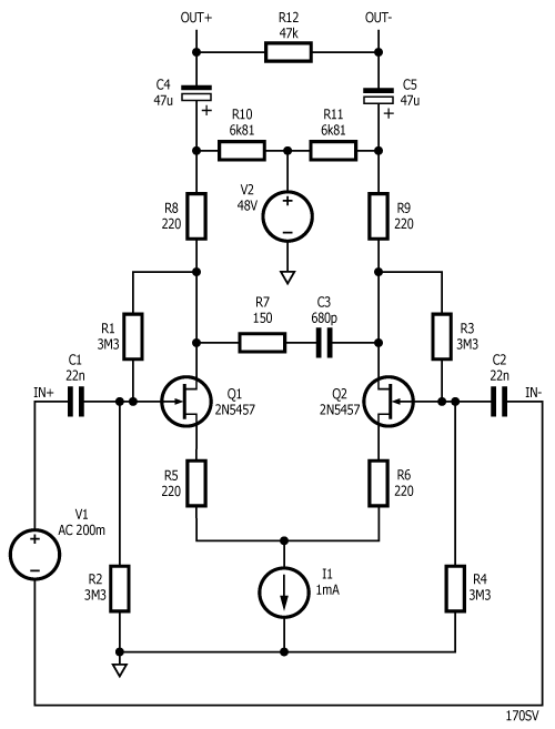
A few years ago, Alex Rice put a design up on the internet for a phantom-powered JFET piezo preamp. Here’s the schematic of the original design as reported by Zach Poff:

So far so good. Q1 and Q2 are cited by Alex as a matched pair of N-channel JFETs with Idss 1-2mA and that Q3 should sink 1mA, giving a 0.5mA bias to each of Q1 and Q2. R5/R1 and R6/R2 bias their respective JFETs. R5 and R6 provide a little negative feedback and R4/C1 forms a Zobel network to reduce high-frequency ringing (oscillation) in the cable. Alex Rice claims that the final design evolved as a result of “a lot of fiddling around with circuit simulators and breadboarded prototypes.”
Now I’m no expert at analog simulation, but I have played fairly extensively with LTspice and the above circuit does not appear to work. It seems obvious that the value of C2/C3 is really rather low and therefore the low-frequency response of the above circuit is not going to be very good. I simulated the design in LTspice like this:

Q3 is replaced by a 1mA constant current source; The input is an ac voltage source; R5, R6 and V2 represent the phantom powering circuitry in the mixer; and C3, C4 and R7 represent the early part of the input stage of the mixer. We’ve left the Zobel network out because we want to see how the circuit simulates without it. We take our output from the differential voltage OUT+~OUT- which is approximately what the high-impedance differential-input-stage of the mixer-preamp will see.
Note: Please read Phantom Piezo Preamp revisited for updates and corrections.
The simulation command is .ac dec 20 1 20Meg to give a small signal response from 1Hz to 20MHz.
The above circuit simulates with a lower -3dB point at 2.2kHz and the output is down by 41dB at 20Hz. This directly contradicts Alex Rice’s assertion that the frequency response is down by only 3dB at 20Hz. And this is as you would expect. Each side of the input signal is going to see a low pass filter formed by the input capacitor and the input resistors in parallel. If we lump all the input resistances together we get (R1+R3) || (R2+R4) to give 3MOhms a.c. input resistance and 220pF in series with 220pF to give 110pF input capacitance. Therefore, the input signal sees a high-pass filter with a corner frequency of 1/(2 x pi x R x C) = 482Hz, which is considerably higher than 20Hz.
If we increase the value of C1 and C2 to 22nF and increase R1~R4 to 3.3 MOhms, the -3dB point falls to 22Hz, which is more like what we would want.
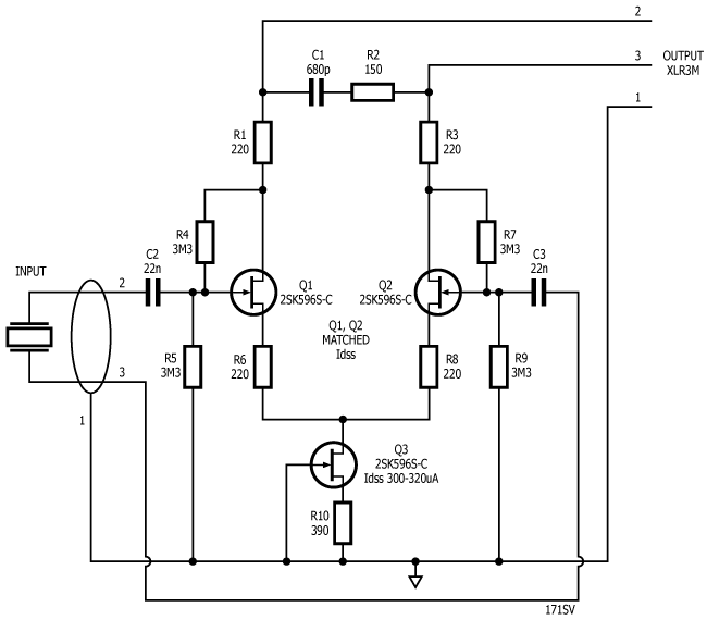
Now, the high frequency response of this design is theoretically 3dB down at 25MHz so we definitely want to incorporate some roll off. Alex also mentions adding source resistance to Q1 and Q2 to reduce the gain and series resistors in the output lines to further reduce the likelihood of oscillation in the cable between the preamp and the mixer. This gives the following topology:
This simulates with a -3dB frequency response of 18Hz to 21kHz. Note that the capacitor in the Zobel network (C3 above) has been increased from 220pF to 680pF. If you further increase C3 to 1nF, the upper -3dB point will reduce to about 14kHz. The gain of the circuit is somewhat dependent upon the input impedance of the mixer and with R7 at 47k, gain is about 15.5dB. I simulated this design with various JFET models and they all give broadly similar results. The major effect is differences in nominal transconductance affecting the gain.
The point of the exercise is to find a use for the 2SK596S JFETs I just bought and characterised (and indeed put on sale here). The ‘596 features comparatively low Idss. Unfortunately, there doesn’t seem to be a spice model kicking around, so we can’t simulate it in the above circuit topology. However, we can characterise the Idss and figure out a suitable value for the current source:
We finally settled on and built this design on a small PCB with a Neutrik NC3MAAH-1 pcb-mount XLR connector:

Initial tests give good results. The next plan is to build a wooden stomp box and give the design a proper workout. Phantom Piezo Preamp modules are available to buy in the shop here.
So what can this design be used for? Well, it can be built into all kinds of instruments that have a piezo pickup element, whether that is a commercial pickup or a home-brew piezo disc glued or taped onto a resonant surface. Also, you could install it into a guitar or bass (the PCB envelope without the XLR and input sockets fitted is 37mm x 29mm x 9mm high) and give your instrument a balanced active output. You can use it as a hydrophone preamp or as part of an art installation.
Please see Phantom Piezo Preamp revisited for updates and corrections.
As the unit must be phantom powered (and there is no battery option), the design is suitable for semi-pro or professional use where there will always be a mixing desk with phantom power available (and a sound guy who’s not afraid to use it). ![]()
Hello
I was wondering if it’s possible to:
– add a volume control by replacing one resistor with one log pot (which resistor? have you any suggestion on the specific pot type?)
– add an external DPDT in order to bypass the preamp if needed (I guess there are no issues with this)
Thank you
The design as shown has about 12dB of voltage gain. You will get better noise performance by adjusting the gain/trim/pad at the mixer.
As the design is fully balanced, there is no obvious place to put a volume control. Changing the values of R6 and R8 (figure 171SV, above) will affect the gain, but if you replace R6 & R8 with a dual-gang volume control you will inevitably destroy the balance of the circuit.
Finally, I don’t know why you would want to bypass the preamp. The point of the preamp is that a piezo element does not have low enough output impedance to drive a cable of any significant length so if you bypass you will lose all your high-end frequency response. However, using a DPDT to bypass will work.
If you want a piezo pre with volume control, you should consider the Altoids Piezo kits which are covered in the blog and available in the shop. HTH.
I don’t understand why replacing 2 resistors with 2 variable resistors (synchronized, so the value is the same apart from each resistor’s tolerance) should unbalance the circuit.
For sure I’m missing something, could you explain it to me?
For the DPDT: it’s just to play even if a phantom power it’s not available: I will come back to my current sound but I can still play without it.
Dual gang pots are notoriously unbalanced at the best of times but there’s no reason why you shouldn’t experiment.
Is it just because I should use the same value on R1, R3, R6, R8?
In such a case could I use a quad-gang pot to solve the issue?
R1 and R3 are doing a different job to R6, R8. It is coincidence that the values are the same.
What a great article. I made the original design a while a go, but put it aside because I wasn’t really satisfied with the results.
I still have a bunch of J201 JFETs. How can I use these, using your modified preamp diagram?
My guess is that the values of R1, R3, R6, R8 and R10 have to be altered, but I don’t know how.
Thanks in advance.
Hans
Thanks for your kind words.
R1 and R3 are there to prevent instability in long cable runs – no change required. R6 and R8 set the gain – no change required. To substitute JFETs, you need to change R10 which sets the bias current. Anywhere between 0.5mA and 1mA should be fine. Put a resistor in (say 2k2) and measure the voltage drop. Use Ohm’s law to get the current. Change R10 as appropriate. Don’t forget you need very well matched parts for Q1 and Q2 to get good results.
Thanks for your reply.
I’ll make a breadboard setup and fiddle around. If you like I can post the results.
It will take some time before I can start, do.
I’ll make sure that the JFETs are matched.
Excellent write-up.
Was there any particular reason to choose C type j-fets over others? Just in case I cannot get hold of the original type.
Thanks,
-helmut
2SK596S-C is what Mouser stocks. You can experiment with any JFETs you like – see the above comment on substituting JFETs. You need to very closely match J1, J2 for Idss and adjust R10 to set the bias current.
Hello, great article.
Sorry for my English.
How can i connect a commercial not balanced piezo (Shadow SH-712) in this circuit?
Any modification?
THANKS!
Thanks. You might be better off with the Altoids piezo preamp or Altoids piezo DI instead of the phantom piezo preamp. However, you can try two ways to connect the Shadow to a Phantom piezo preamp. Firstly, connect the Shadow balanced to pins 2 and 3. Secondly, connect the shadow unbalanced by connecting the shield side of the Shadow to pin 3 and Pin 1 and the hot side of the Shadow to pin 2. HTH.
For Q1/Q2, does the Idss value matter as long as they’re matched and R10 is adjusted for the bias current? I’m thinking of using a matched dual JFET so I don’t have to match them myself. 😛
Thanks!
The current through Q3 is shared equally between Q1, Q2. Q3 current therefore needs to be less than two times the actual Idss of Q1/Q2 and also needs to be small to avoid warming up the JFETs (and thus altering their operating point). Also, the higher the current, the more the phantom voltage will be dragged down and thus the lower the headroom. Having said that, the actual current is not super important. The 2SK5956S-C has comparatively very low Idss, so Q3 has a correspondingly small current. If you substitute 2N5457 or 2N5484 (say) Q3 current could be significantly larger. 100 – 250 uA through a JFET is plenty enough to bias it.
Thanks for the answer.
I have seen both the Altoids piezo preamp and Altoids piezo DI. These look fantastic, and I will build them in the future, but for my project these are too big for what i need
I had try the two ways sugested:
1.- I Connect the hot side of Shadow to In1 and the shield to In2, and (logically) get too much noise.
2.- I connect the hot side to In1 and the shield side to In2 and ground: Sound well, but with reinforcement of low frecuency (I recorded and compared to sound with Behringer D.I.
May be that supressing zobel network (r4, c1) the sound will be better?
Thanks
(and sorry for my english..)
The Zobel network only has any effect on the high-frequency response. Without the Zobel, the circuit 170SV above simulates a upper frequency limit of about 25MHz. With the Zobel shown, the high frequency response is reduced to 22kHz (-3dB). As the circuit stands, it simulates with a low frequency response down to 18Hz (-3dB) balanced, so why you are getting a reinforced low frequency when you connect unbalanced, I have no idea.
Hi All,
I’m new to electronics and just recently bought the piezo preamp. I have a question regarding floating-grounds and optimising my setup n general. Here’s how I’ve used the preamp so far:
I housed the preamp in a small tupaware tub insulated on the inside with aluminium tape. The xlr socket is accesible on one side of the tub, a minijack socket is accessible on the other to allow different contact mics to be plugged into the pre-amp. I have wired the pre-amp ground and neutral to the sleeve of the minijack socket and the positive to the tip.
This has improved the recordings I can make ten-fold. However I still hear a slight 50Hz ground (?) hum and would love to improve this setup get a silent signal and improve the signal-to-noise ratio further. Have I wired this correctly? Is aluminium tape better or worse than copper for insulating the box? Am I making any fundamental errors?
Any advice you can give me would be much appreciated.
Cheers!
Aluminium tape is just as good as copper for shielding provided you get a good electrical connection to the aluminium tape (which has a hard non-conductive oxide layer). Copper tape is better because the overlap has good conductivity and you can easily solder a wire to it to connect to pin 1 of the XLR (or the ground contact on the input connector). Regarding the input jack – it seems you are using a mono jack and thus connecting your input unbalanced. This is less satisfactory from a hum point of view than connecting your input balanced.
Thanks for your response. Is there any way of wiring a single piezo to a balanced jack to minimise the hum? I read the Stompville article on un/balanced audio and have searched online but it seems the only way is with two piezo’s. I feel like I’m missing something!
Thanks for your time, much appreciated.
Well, yes. You wire the piezo as per the schematic above. One connection to the piezo to pin 2, the other to pin 3 and the shielding to pin 1. Ensure that neither connection from the piezo is grounded. This is the minimum-hum configuration. You need to shield the piezo element, the input cable to the preamp and the preamp itself.
Ah, I think that’s called ‘not seeing the wood for the trees’! Thanks so much for your help, I can’t wait to wire this up.
Cheers!
Thank you for the article, excellent !! I showed the original Alex Rice schematics to my friend who has experience in electronics and his first reaction was that the 220pF cap were WAY too small…
I have two question, I would like to build the above, but do not have phantom power (I’m building this for my wife’s sitar, and we do not connect to a mixing board, so no phantom power). Is there any way to use just a battery ? Ideally a 12V, but I could use a DC-DC converter to raise the 12V to 24V-32V if needed…
Second question: what is the output of this preamp ? I plan to connect the preamp to a Bluetooth transmiter that accepts 0.1V-2V input and I don’t want to overdrive it.
Thank you very much, Alex
The Phantom Piezo design design is specifically for connecting to Phantom-power mixing desks. There is no point in trying to finesse the design for any other circumstance. For your application you should consider the Altoids piezo preamp design http://stompville.co.uk/?p=224
The output will likely be in excess of 200mV, so you will need a volume control at the output of the preamp (or change the ratio of R4 and R5 to give fixed attenuation). HTH