Some years ago I designed a theatrical cue-light system and I recently came across the drawings. The system was based on relays and I thought it would be interesting to see how cue-light designs have progressed over the years. I found that there are many different ways of doing cue lights and I thought I would gather together some of the ideas floating around the interwebs and present them here.
Note that the circuits presented here are not complete designs and there are many and varied engineering considerations which will make any final design more complex than the schematics here show. Some components, such as bypass capacitors, input protection diodes, etc have been omitted for clarity. There will be projects later which are suitable for building and deploying in a professional environment.
Note that I have used the word lamp to describe whatever lighting technology is in use. However, any new system will likely use light emitting diodes (LEDs) rather than incandescent lamps.
What are cue lights?
Cue lights (or Q lights or Q lites) are a visual signalling system operated from the stage manager’s desk and are used to signal cues to stage-hands and performers. The system comprises a control station at the stage manager’s desk (from where the system is powered) and one or more outstations. Each outstation has a minimum of a red and a green lamp (usually LED) and often incorporates a switch to signal back to the control station. In traditional systems, the cue lights are hard-wired. Wireless (radio) systems are available but we will not consider them here.
Cue light systems may be integrated into the structural wiring of the building or may be entirely portable. In the first case, cabling will be permanently installed to various locations. These cables may be directly terminated to fixed outstations or may be terminated at a connector plate (in which case it is usual to fit a 3-pin XLR). 3-pin XLR connectors are also fitted to portable outstations so that standard microphone cables may be used (also, audio tie-lines may be pressed into service for cue-lights if needs be). The standard audio convention for XLRs should be followed (signal comes out of pins – think of a microphone), so the fixed infrastructure should have a male XLR and the portable outstation should have a female XLR. Tie-lines for cue-light outstations should be numbered to avoid confusion – names can be flexible; numbers should always be unambiguous. In a large venue there may even be a patch-panel as there may be more outstation positions/tie-lines than there are control channels.
How are cue lights used?
Each outstation has a red lamp and a green lamp. The idle state is both-lamps-off. The red lamp (STANDBY) is switched on indicate a cue is imminent. The green lamp (GO) is switched on to indicate that the cue should happen immediately. The red light and green lamps are not on at the same time. After a GO there may be an idle period, or the operator may immediately re-select STANDBY if a second cue follows directly after the first. On many systems it is possible to go straight from idle to GO (i.e. without STANDBY) – but this usually only occurs if there are a number of cues very close together and use of STANDBY would make cueing too slow.
Outstations often have a switch as well as red and green lamps. The switch is used to signal back to the operator station that the stage-hand or performer is ready and waiting for the GO. On simple systems the switch causes the STANDBY lamp to extinguish whilst the button is pressed. This has the disadvantage that the operator at the master station needs to look out for the momentary extinguishing of the STANDBY lamp. A more sophisticated option is to have the STANDBY lamp flash continuously – then, when the button is pressed at the outstation, the STANDBY lamp stops flashing and lights continuously.
Some control stations have a master or assign function. There are two ways to implement master. The simpler way is to have a MASTER-GO switch make every channel that is currently on STANDBY change to GO. The more complex way is to assign individual channels to one or more master channels then have STANDBY and GO buttons for each master-channel. More on this in Part 3.
Arrangement of lamps
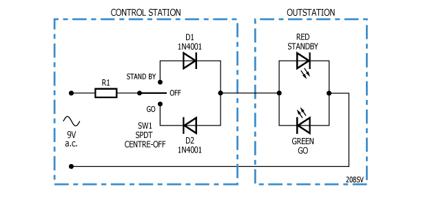
Usually, the lamps at the control panel are in series with the lamps at the outstation. This gives the operator confidence that the outstation is connected and working. If the operator switches to STANDBY but the STANDBY lamp on the control station does not light, the relevant outstation is likely unplugged, missing, damaged, plugged into the wrong tie-line or mis-patched – or a noise-boy nicked the XLR cable.
Two-wire systems
This is the simplest design cue light channel and it uses a two-wire cable: This about the lowest cost design possible and works on the basis that that diodes and LEDs only conduct current in one direction. When switch SW1 is in the centre-off position, no current flows in the circuit. If SW1 is set to STANDBY, D1 blocks current to the green LED and the red LED illuminates. If SW1 is set to GO, D2 blocks the current to the red LED and the green LED illuminates.
However, we should replace D1 and D2 with another pair of red/green LEDs, so that the control station illuminates as well as the outstation; and we should have separate resistors for each colour in case they need to be different values: Finding a value for the current-limiting resistors R1 and R2 is a little tricky:
- The mains voltage may vary – we have to live with this
- The mains transformer is unregulated – we can allow for this
- The LED in the control panel may need to be dimmer than the LED in the outstation – see below
Matching LEDs and luminous efficacy
LEDs have a characteristic called luminous efficacy. This is akin to efficiency and indicates how bright an LED is going to be for a given power dissipation. Luminous efficacy is measured in lumens/watt. However, since the forward voltage drop is fairly constant we usually think of luminous efficacy in terms of current. Two identical LEDs in series will pass the same current and will therefore exhibit the same brightness (within a tolerance range, natch). However, we generally want the LEDs at the control station to be dimmer than the LEDs at the outstation. There are two ways to deal with this. Firstly, you can select an LED with lower luminous efficacy for the control station and higher luminous efficacy for the outstation. Thus for the same current, the outstation LED will be brighter. Alternatively, you can use a mechanical method to (such as a neutral density filter) to reduce the brightness of the LEDs in the control station.
Red LEDs typically have higher luminous efficacy than green LEDs so you should always allow for separate resistors for the red and green current paths.
In summary, you need to experiment to find suitable LEDs and resistors for your particular operating conditions. You could even have some outstations fitted with super-efficient LEDs to get the brightness you need for a particular location around the venue.
Calculating a starting resistor value
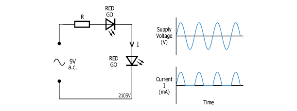
Let’s simplify the above schematic: Let’s say we are using a nominal 9V @ 1A wall-wart power supply. The transformer will have about 20% regulation so – with only two LEDs connected – the voltage is going to be about 9 + 20% = 10.8V a.c. However, as we can see from the lower graph above, the a.c. is being half-wave rectified so the current is only flowing half the time.
Let’s say we choose a nominal current of 20mA and the LEDs both have a forward voltage drop of 2v @ 20mA. To get the LEDs up to full brightness we need to double the current to 40mA to compensate for the half-wave rectification.
The voltage across R is 6.8V (the supply voltage (10.8V) less the voltage drops of the two LEDs ). The current through R is 40mA. So from Ohm’s law (R=V/I) the value of the resistor R1 is 6.8V/ 40mA = 170 Ohms.
We should experiment with 150Ohm or 180Ohm resistors (or a greater range – this calculation is just a starting point) to see how we like the brightness of the LEDs. Note that as we add more channels (or rather as we have more channels simultaneously in use) the transformer voltage will drop and all the LEDs will get a little dimmer. We could split the difference and use a value for the supply voltage half way between 9V and 10.8V = 9.9V to average out the effect of regulation.
A further consideration is that the longer the cable between the control station and the outstation the dimmer the LEDs will be (due to the resistance of the cable).
Two lamps and a button
We can add a simple acknowledge/ready button to the outstation by adding a normally closed momentary switch in series with the red LED. The stage-hand at the outstation presses the button a few times to signal to the operator that they are attentive and have noticed the change from idle to STANDBY: If you are on a budget and you are making a portable system, by all means build a system based on the above design. If you choose to use 3-pin XLRs to connect the two boxes, use pins 2 and 3 and leave the shield (pin 1) unconnected to the circuit. If you want to permanently install this system you could use Cat-5 twisted pair or telephone twisted pair (CW1308 in the UK).
In part2 of this series we will introduce automatic flashing standby. ![]()


Thanx very much, this is a great and fascinating document and very interesting (especially the two wire idea)
pj