
In the first part, we covered an introduction to cue lights are and how they are used. We also looked at a simple two-wire system. In this part we are going to look at three-wire systems with automatic flashing.
Note that the circuits presented here are not complete designs and there are many and varied engineering considerations which will make any final design more complex than the schematics here show. Some components, such as bypass capacitors, input protection diodes, etc have been omitted for clarity. There will be projects later which are suitable for building and deploying in a professional environment.
Professional cue-light systems will most likely be installed as part of a venue new-build or refurbishment and typically the same type of cable will be used for cue-lights as that for audio. This is usually a foil-screened twin type such as Belden 8451 or similar. As the cue light system works on relatively low voltage, it is often wired with 3-pin XLR connectors so that if necessary, tie lines can be shared between audio and cue lights – and so that standard microphone flexible cords (or 3-pin DMX cords for that matter) can be used to connect up the outstations.
If possible, we will want to maintain the shield of the cable (XLR pin 1) at ground potential and use pins 2 and 3 for signalling. We could implement the two-wire system from Part 1 on 2-core cable and if so we should use the two signal cores (pins 2 and 3) and leave the ground alone.
Having said that, our first goal for expanding on the basic system is to introduce automatic flashing for the STANDBY function. When the operator at the stage manager’s desk selects STANDBY, the red lights at the control station and the outstation will flash until the stage-hand at the outstation presses the READY button on the outstation. The system will detect the button press and latch the STANDBY lamp so it stops flashing and remains on continuously.
Making a flasher
There are several ways to make a flasher; we need a frequency of around 1Hz and a square wave output with about 50% duty cycle.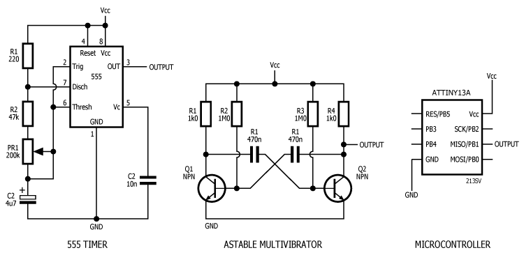
Firstly we can use the venerable 555 timer; I generally use the TLC555 CMOS version. As R1 is small compared to the value of R2 + PR1, the duty cycle is very close to 50%. Adjust PR1 to set the frequency between about 0.6 Hz and 3.2 Hz.
Another option is the two-transistor astable multivibrator; the values shown give a frequency of about 1.5 Hz.
Finally, you could use a microcontroller to get practically any frequency you like.
None of the above circuits have the capability to deliver significant current, so a PNP transistor or P-Channel MOSFET is required to switch enough current to flash all the channels in your system. The transistor or MOSFET could be replaced with almost any power device with similar or better performance; the types shown are inexpensive TO-220 packages. Note the difference in the value of R1 between transistor and MOSFET. The MOSFET is more expensive, but dissipates less power (and so requires a smaller heatsink).
Switching to a d.c. powered system
In Part 1 we introduced a simple two wire system using an a.c. supply: In order to implement latching STANDBY, we first need to change to a d.c. system and we do this by changing out SW1 for a double-pole switch:
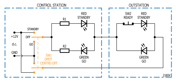 When we are in STANDBY, we apply +12V to R1 and ground the return wire from the outstation. When we are in GO, we ground R2 and apply 12V to the return wire.
Latching STANDBY version 1
We need to add a relay and a connection to our flasher circuit: We start with switch SW1 in the idle (centre-off) position. When we switch to STANDBY, R1 is connected to the flasher circuit through RL1/1 and the outstation return line is connected to ground. If we press the READY button, RL1 switches STANDBY over to continuous +12V. At the same time, RL1/2 latches the action of the READY push button so when we release the READY button, the STANDBY lamp does not revert to flashing.
When we return to idle (either because we cancelled the STANDBY or because we are switching through to GO), we disconnect the ground from the relay coil and the relay drops out.
When we switch to GO, R2 is grounded and +12V is applied to the outstation return line, so the GO lamps light.
Nothing happens if you press the READY button when SW1 is in GO.
Practically any style of DPDT relay may be used. It needs to have a 12V d.c. coil. For flexibility, I would specify an industry-standard-footprint relay such as an Omron G5V-2 12DC. Practically every manufacturer makes this style of relay so just buy the cheapest you can get on the day. The G5V-2 is a PCB-mount relay. You could alternatively use an industrial-control style of relay such as the Omron G2R-2 plug-in series which have matching chassis-mount sockets.
The advantage to this design is that it is simple and reliable. The disadvantage is that we are applying +12V to the ground wire – which is bad if we want to integrate the cabling.
Latching STANDBY version 2
If need to ensure that the shield wire of the installation cable remains at ground potential (which is likely in a professional permanent installation), we have to implement a split 12V supply. In this configuration, XLR pin 1 remains at ground potential; pin 2 has +12V or -12V (with respect to ground) to light either the STANDBY or the GO lamp as required and pin 3 is used for the READY signal.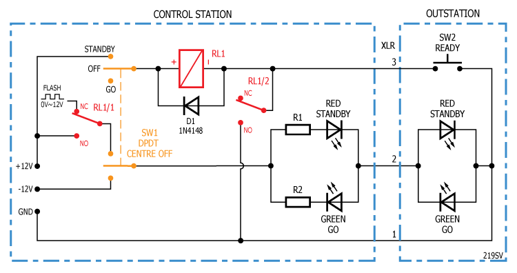 Operation is very straightforward. Switching to STANDBY puts +12V flashing on R1 and the STANDBY lamps light. Pressing the READY switch pulls in RL1 which switches over to continuous STANDBY. Again RL1/2 latches the action of the READY switch. Switching over to GO puts -12V on R2 and the GO lamps light. Switching away from STANDBY releases RL1. See version 1 for a discussion of suitable relay options for RL1. This design is an excellent candidate for a relay-based non-master professional installation.
Latching STANDBY version 3
An alternative to 555 timer and relays is a microcontroller. There are various ways of implementing this and the simplest is to use one microcontroller per channel: We could use a microcontroller with more pins to control multiple channels but then we would have to worry about the total amount of current the microcontroller could deliver. Also, if the microcontroller fails only one channel is affected. The disadvantage of this design is that if you have multiple channels on flashing standby, they will not be flashing in unison as each microcontroller generates its own flashing signal in software.
The XLR pin 1 connection is at ground potential so this makes it safe to inter-operate with audio tie-lines.
The software might be configured as follows:
- In idle mode pressing STANDBY switch flashes the STANDBY lamp
- A further press of the STANDBY switch cancels STANDBY and returns to idle
- Pressing the READY switch in STANDBY mode causes the STANDBY lamp to light continuously
- Pressing GO at any time switches off the STANDBY lamp and switches on the GO lamp
- Pressing the STANDBY switch cancels the GO back to idle
The software reads the status of the READY switch by periodically changing PB2 to be an input and then reading the analogue voltage at PB2. When the READY switch is closed, the analog voltage at PB2 is about 3.4V. When the READY switch is pressed, the voltage at PB2 rises to 5V.
The control input could be used for a MASTER GO input. The software would be configured so that if (and only if) the channel was in STANDBY mode, then a signal on the MASTER GO input would change the channel to GO mode. Alternatively, the control input could be used as a flash sync input so all flashing channels flash in unison.
In part 3 we will look further at master modes. ![]()