In part 1 we introduced cue light systems and discussed simple 2-wire a.c. systems. In part 2, we introduced d.c. switching and moved on to latching STANDBY. Later in part 2 we introduced a microcontroller-based design.
In this part we will consider adding MASTER GO to relay systems and then expand on microcontroller-based designs.
Note that the circuits presented here are not complete designs and there are many and varied engineering considerations apply which will make any final design more complex than the schematics here show. Some components, such as bypass capacitors, input protection diodes, etc have been omitted for clarity. There will be projects later which are suitable for building and deploying in a professional environment.
As introduced in part 1, there are two basic flavours of MASTER GO. In the first instance, a MASTER GO switch turns every channel which is currently in STANDBY to GO. This is trivial with a microcontroller based system. The alternative system is to manually assign channels to one or more MASTER GO channels. It is likely that any more than two master channels would be too unwieldy to keep track of unless you have a fully programmable show-control front end to your cue light system.
Manually assigned MASTER GO
Adding master functionality to our relay-based cue-light system makes the system somewhat more complex as we need to add two relays and two more switches. The problem of course is that when we are in master mode, we need both to light the GO lamp, but also cancel the STANDBY. This means an extra relay to manage STANDBY and an extra relay to switch from STANDBY to GO: We start with all three relays in the off state.
We press SW1 to enter the STANDBY mode. RL1 is energised and RL1/2 latches STANDBY. RL1/1 closes and the STANDBY lamps flash.
If we press CLEAR (SW2), the system returns to idle mode.
If we are in STANDBY and we press READY (SW4), we energise RL2. RL2/2 latches the action of SW4 and RL2/1 switches the STANDBY lamps from flashing to steady.
Again if we press CLEAR (SW2), STANDBY is cancelled and the system returns to idle mode.
At any time (irrespective of the STANDBY status) we can switch the master switch SW3 to either GO – in which case we get an immediate GO – or MASTER – in which case the channel will GO when the MASTER GO signal is switched to +12v. Either way, RL3 is energised. RL3/1 switches the lamps from STANDBY to GO and RL3/2 de-energises RL1 and RL2 thus cancelling STANDBY mode and reverting to flashing. SW3 is usually a centre-off type with one side (master) latching and the other side (immediate go) spring-biased.
Expanded microcontroller design
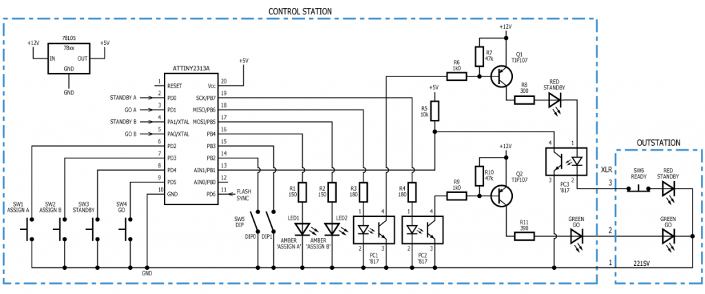
In part 2 we introduced a cue-light design based around an 8-pin microcontroller. If we switch to a 20-pin device we can expand the functionality of the design: Here we have five signals coming from a master module (not shown). These are STANDBY and GO for MASTER A and MASTER B. There is also a 555 timer generating the flashing signal. This signal is input to each channel as FLASH SYNC so that channels flashing in STANDBY are synchronised (i.e. flash together).
For this version we have introduced optical isolation of the outstation to protect the control station from noise and interference. Also, Q1 and Q2 have been changed up to TO-220 Darlington devices. Note that the value of R8 is less than that of R11 because there are three LED’s in this chain and we have to account for the extra forward voltage drop of the infra-red LED in PC3. The microcontroller software detects the READY condition by monitoring the output of PC3. If the current in PC3 is zero when it should be 20mA, the READY button must be pressed. R5 pulls up the input PB1 when PC3 transistor switches off.
The software in the microcontroller might work thus:
- If the channel is assigned to master-A or master-B (or both), the channel will respond to appropriate master signals. Otherwise the channel will ignore master signals
- Pressing ASSIGN A or ASSIGN B will assign the channel to the respective master-channel. Pressing again will cancel. The amber-coloured LEDs will show the assign status.
- Pressing the STANDBY switch will set STANDBY lamps to flash
- Pressing the STANDBY switch again will cancel STANDBY
- Pressing READY whilst in STANDBY mode will cause the STANDBY lamps to light continuously
- Pressing GO at any time (i.e. from idle or STANDBY mode) will cancel STANDBY and light the GO lamps
- Pressing STANDBY or GO will cancel GO mode and return to the idle state
DIP switches DIP0 and DIP1 may be used to set user preference options, e.g.:
- Option 0 – GO is momentary
- Option 1 – GO is latching until STANDBY is pressed to clear the GO
- Option 2 – GO is on for 5 seconds then cancels automatically (unless manually cleared by STANDBY)
- Option 3 – GO is on for 10 seconds then cancels automatically (unless manually cleared by STANDBY)
If the unit is in MASTER mode, GO should remain active until manually cancelled (i.e. always Go option 0).
In part 4 we will consider special-use outstations. ![]()
