
Updated 1st December 2019
Part 3 of this series introduced two professional cue light systems both using a three-wire system with an XLR grounded cable shield. One system is relay-based and the other microcontroller-based. Either system would be suitable for a professional installation. However, the two systems use different arrangements for the outstation. In fact there is no standard design for outstation wiring and you should make no assumptions about your system – you must dismantle an outstation and check with a multimeter to be sure how your system operates – it may have a.c. or a single or split d.c. voltage and the READY switch may be normally open or normally closed. The voltage might be anywhere from (say) 6V to 48V.
In this article we are going to consider how we can connect other than the standard outstation to the cue light system.
WARNING!
You may be tempted to use your cue-light system to fire pyrotechnics. This may turn out to be a very bad idea.
DO NOT FIRE PYROTECHNICS DIRECTLY WITH YOUR CUE LIGHT SYSTEM without first fully discussing the safety implications in a properly-convened production meeting where all interested parties are allowed the opportunity to pour scorn on your head and veto your cunning plan with extreme prejudice.
Don’t forget that one of the most important safety rules for stage pyrotechnics is that the person who presses the fire button should have line-of-sight to the pyrotechnic device. Cue-light systems are generally used for those situations where the operator does not have line-of-sight. This sort of paradigm conflict could be the first step on the road to disaster.
Outstation design variations
A review of the outstation designs we have introduced in this series of articles reveals four basic designs: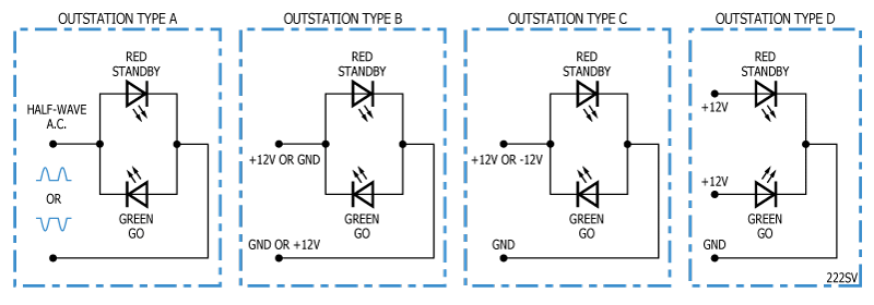 As previously noted, any good cue light system will have the lamps at the control station in series with the lamps at the outstation to give confidence that the outstation is working. We could make a reasonable assumption that the current is in the order of 20 mA and that the expected voltage drop at the outstation is about 2V.
Note that the following designs are good for Type B, C or D (i.e. d.c.-powered) outstations only.
Ohm’s law again
This is the calculation for the LEDs in the control station and the outstation: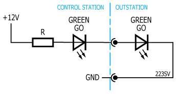 We will assume a voltage of 12V. We will assume that each LED will drop 2V. We will assume that the current flowing in the LEDs is 20mA. Therefore, we have what we need to calculate the value of resistor from Ohm’s law R = V/I.
The voltage across the resistor is 12V – 2V – 2V = 8V so the resistance required is 8V/0.02A = 400 Ohms.
If we want to connect a different type of load to the cue-light system, we either have to work within the above limits or we have to provide an auxiliary power supply for our load.
Replacing the LED with a photocoupler
We can replace the LED in the outstation with a photocoupler (also known as optocoupler or opto-isolator). Many jelly-bean photocouplers will do and a good starting point is any device with 817 in the part number e.g. Sharp PC817, Kingbright KB817, Fairchild FOD817, Vishay K817, Avago HCPL-817, etc – they’re all much the same and all have UL approval for mains isolation. Don’t use a photocoupler with 814 in the part number as these have back-to-back diodes and will likely not work as expected.

Note that the photocoupler must be wired the same way as the go LED in a ‘normal’ outstation.
Here the photocoupler is directly driving a light-duty power relay such as the Tyco OJ-SS-112LMH. This relay is good for up to 8A of load current. There are various flavours of this relay – make sure you get a version with 112L in the part number as the L represents the sensitive coil version and also make sure you observe the maximum load current limit. The 12V supply on the outstation side is local to (and independent of) the control station. For isolation, the ground from the cue-light system and the ground from the local 12V supply should not be connected. If you require a local voltage other than 12V d.c. that’s fine, but be aware that the ‘817 photocoupler has a Vceo of 35V, and you don’t want to get too close to that so you should limit yourself to about 28V d.c. on your local supply. If you change the local supply voltage, you must change the relay shown for one with a suitable coil voltage and you must recalculate a value for R1.
If the relay in the above design will not switch enough current, then why not use the above circuit to switch the coil on a bigger relay – such as the Omron G7L.
Switching AC mains with an SSR – Updated Dec 2019
If you want to switch mains with your cue-light control station, one option is get a hockey-puck-style solid-state-relay (SSR) such as the Omron G3NA: This type has the advantage of not requiring a great amount of additional work:
Again, the input of the relay must be connected the correct way round to match the polarity of the GO lamp in a ‘normal’ outstation.
The Omron G3NA-210B is good for 10A. If you are planning to run a heavy load for any length of time you need to be sure that there is adequate heat sinking for the SSR. The double-pole power switch is included because solid-state relays are not regarded as mains-isolating (for safety) when off.
Update: However, the problem with Solid State Relays (SSR) is that you must have a minimum load for them to work correctly. If you use an SSR to switch a product powered by a switch-mode power supply (SMPS), you may find is does not work well. This is because the SMPS only takes current during part of the cycle and, as soon as the current drops to zero, the SSR switches off causing a problematic interaction between the two. Even for resistive loads (incandescent lamps count as resistive for this purpose) there is a minimum load. For example, the above Omron SSR G3NA-210B has a minimum load current of 100mA (23W @ 230V). Consequently, you really need to figure out if your intended load is suitable for use with a particular SSR.
The input circuit of the SSR is rated at nominal 5-24V d.c. but is current limited to 7mA. This means that the GO lamp in the control station will likely be dimmer-than-usual when lit.
Let us assume a 12V supply and a 2V drop across the GO lamp in the control station and that R is approximately 390 Ohms to give a nominal current of 20mA. The SSR will limit the current to 7mA. The volt drop across the 390 Ohm resistor will be 390 Ohms x 7mA = 2.7V. The SSR will therefore see an input voltage of 12 – 2 – 2.7 = 7.3V. This is above the minimum of 5V so will work fine.
The datasheet for the Omron G3NA offers guidance for improving EMC performance:
 Note that C2 must be rated for connection across the mains. Such capacitors always have X2 written on them and are often covered in national approval logos:
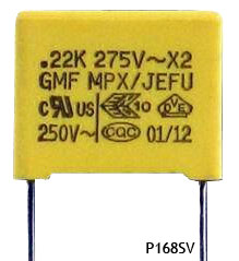
Do not build or work on mains equipment unless you are competent to do so. At the least, show your work to a competent person and ask for their comment and/or approval. Don’t forget to make sure you earth (ground) metallic enclosures. Do not imagine you are competent to design a double-insulated Class II appliance.
This is the end of this series for now. Articles will be updated as errors are brought to my attention. I will work up some projects for you to build.
Finally a reminder that the circuits presented here are not complete designs and there are many and varied engineering considerations which will make any final design more complex than the schematics here show. Some components, such as bypass capacitors, input protection diodes, etc have been omitted for clarity. Some of the schematic drawings have been drawn according to a particular convention so as to indicate how they work. In practice, the design would be developed to make it more robust (at the expense of being a little less easy to understand at a glance). ![]()