Update: Kits now available in the shop here.
Update: Carsten posted a YouTube video here.
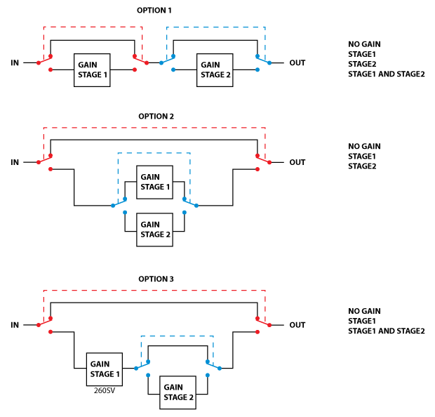
Carsten Møller of Møller Mod in Denmark got in touch to enquire about modifying the Stompville True Bypass Relay project to make an A-B switcher. After a few emails and some discussion, we agreed on a specification and we present the latest Stompville project: An A-B Switcher with two relays to facilitate true overall bypass and selection of A or B effect when not in bypass mode. Carsten initially intends to use the board to make a dual-channel drive pedal. We discussed different ways of achieving this:
You can see that the different topologies give different options for what may be selected. We chose option 2 because when the effect is in bypass, the signal is only passing through one relay.
Our design has two stomp switches and two relays. We will refer to the switches as A and B and the relays as the bypass relay and the select relay. The relays are latching and have a reset (NC) position and a set (NO) position.
- When the system is in bypass mode, the bypass relay is reset.
- When the effect is on (A mode or B mode), the bypass relay is set.
- When the A switch is pressed, the select relay is reset (A mode).
- When the B switch is pressed, the select relay is set (B mode).
There are three LED outputs:
- Power status.
- A is active.
- B is active.
Let’s start in bypass mode. The bypass relay is reset and LEDs 2 and 3 are off:
- Pressing A switch sets the bypass relay and resets the select relay. LED 2 is on.
- Pressing B switch sets the bypass relay and sets the select relay. LED 3 is on.
Starting from A mode. The bypass relay is set and the select relay is reset. LED 2 is on and LED 3 is off:
- Pressing A switch resets the bypass relay. LED 2 is off. (i.e. back to bypass).
- Pressing B switch sets the select relay, switches LED 2 off and switches LED 3 on. (now in B mode).
Starting from B mode. The bypass relay is set and the select relay is set. LED 2 is off and LED 3 is on.
- Pressing A switch resets the select relay, switches LED 3 off and switches LED 2 on. (now in A mode).
- Pressing B switch resets the bypass relay. LED 3 is off. (i.e. back to bypass).
To explain this another way, if we are in bypass mode, pressing A or B puts the system into A or B mode respectively. If we press the button that is currently active, we go back to bypass and if we press the button that is not active, we switch to the other active mode.
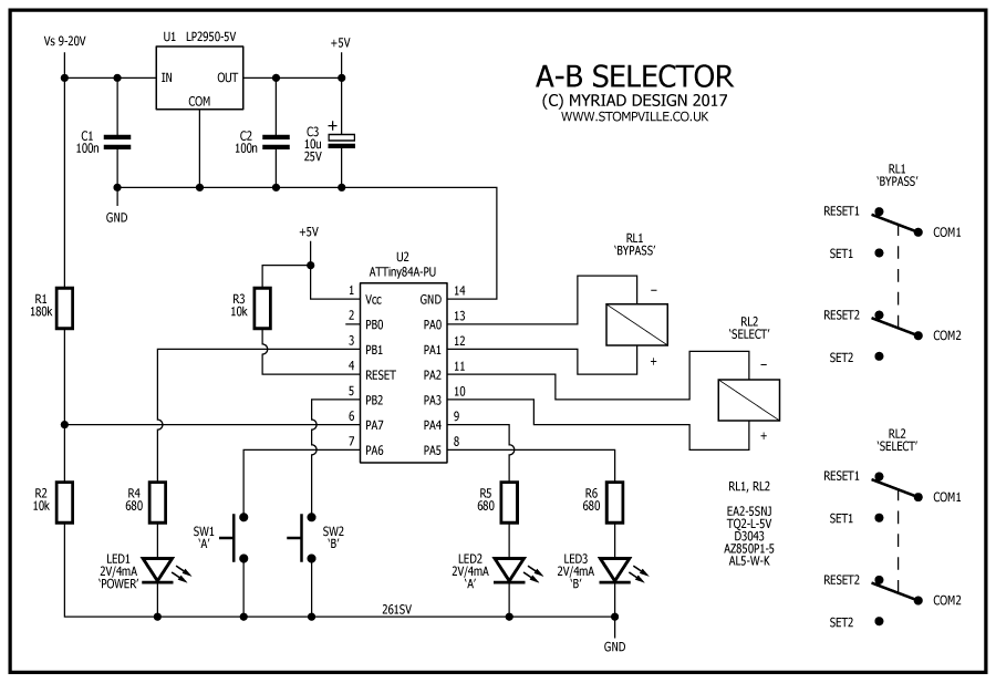
Here’s the schematic:
On the PCB design, all twelve relay pins are available for you to wire them up to your effects however it suits you. Clearly, the hardware design is very straightforward and the logic is in the microprocessor software. In a similar fashion to the original true bypass relay, the power LED flashes ten times if the supply voltage drops below about 8.3V. If you are battery powering the circuit and you want to save the battery, you can omit the power LED altogether and save about 4mA of constant current draw.
Here’s the software development and programming setup:
And here’s the prototype dimensions are 35mm x 34mm:
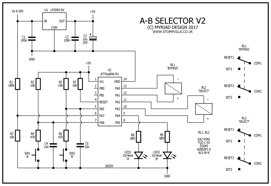
After testing the design in a real project, we decided to make two modifications to the design. Firstly, we would add some more components to the switch inputs to allow the switches to be remote wired. Secondly, we decided we only needed two LED’s not three, and finally, as we are likely not trying to retrofit the PCB into an existing pedal, we should add some mounting holes for the PCB’s. The production PCB’s are 37 x 50mm (with 39mm mounting centres) and look like this: And here is the revised schematic:
Kits are available from the shop. Click here. ![]()


